Makalah ini merinci kepala penghancur kerucut, komponen penghancur inti yang bekerja dengan kerucut tetap untuk menghancurkan material melalui gerakan osilasi, dengan kinerjanya yang secara langsung memengaruhi throughput, granularitas produk, dan ketahanan aus. Makalah ini menguraikan komposisinya, termasuk badan kepala (struktur inti), lapisan aus (mantel), lubang bantalan, fitur pemasangan, dan rongga ventilasi/pengurangan berat, beserta karakteristik strukturalnya. Proses pengecoran untuk badan kepala diuraikan, meliputi ion material (baja cor atau besi ulet), pembuatan pola, pencetakan, peleburan, penuangan, perlakuan panas, dan inspeksi. Makalah ini juga menjelaskan pemesinan badan kepala dan lapisan aus, serta langkah-langkah perakitan. Selain itu, langkah-langkah pengendalian mutu juga ditentukan, seperti pengujian material, pemeriksaan akurasi dimensi, pengujian ketahanan aus, pengujian perakitan dan kinerja, serta pengujian non-destruktif. Proses-proses ini memastikan kepala memiliki kekuatan tinggi, ketahanan aus, dan akurasi dimensi, menjamin kinerja yang andal dalam operasi penghancuran tugas berat.
Detailed Introduction to the Cone Crusher Head Component
1. Function and Role of the Cone Crusher Head
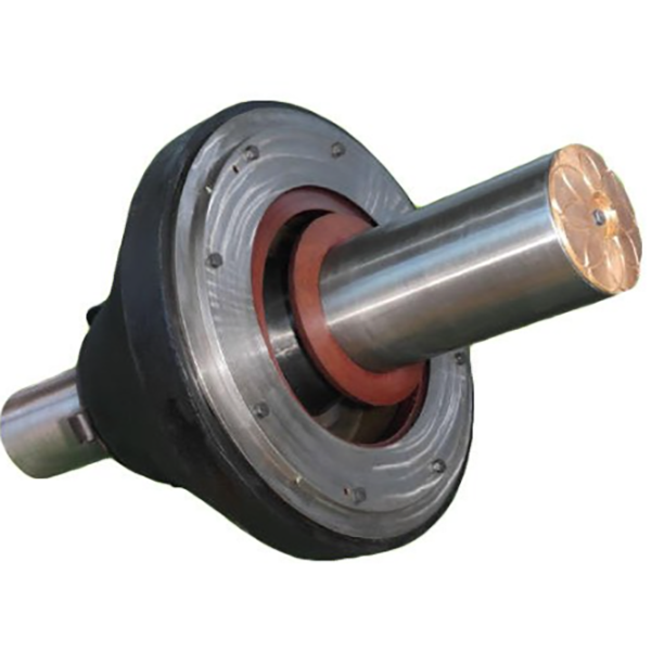
The cone crusher head (also known as the moving cone or 破碎锥) is the core crushing component that directly contacts and crushes materials. It works in conjunction with the fixed cone (bowl liner) to form a crushing chamber, and its oscillating motion (driven by the eccentric shaft) compresses and crushes rocks, ores, and other bulk materials. The head’s shape, surface hardness, and structural strength directly determine the crusher’s throughput, product granularity, and wear resistance. Under high-pressure working conditions, it must withstand intense impact and friction, making it one of the most critical wear parts in the equipment.
2. Composition and Structure of the Cone Crusher Head
The cone crusher head is a composite structure combining a cast iron or steel body with a wear-resistant liner. Its main components and structural features include:
Head Body (Core Structure): A conical or frustoconical casting made of high-strength cast steel (e.g., ZG35CrMo) or ductile iron (QT600-3). It serves as the structural support for the wear liner and connects to the eccentric shaft via a central bore. The body’s inner cavity is designed to fit the eccentric bushing, with keyways or bolts to secure the connection and transmit torque.
Wear Liner (Mantle): A replaceable outer layer made of high-chromium cast iron (Cr20-Cr26) or alloy steel with high hardness (HRC 55-65). It is attached to the head body via bolts, dovetail grooves, or wedge blocks, ensuring tight fitting to prevent movement during crushing. The liner’s surface is often designed with a concave or convex profile (e.g., standard, coarse, or fine crushing profiles) to optimize material gripping and crushing efficiency.
Bearing Bore: A central cylindrical or tapered hole in the head body that accommodates the upper end of the eccentric shaft. The bore is precision-machined to ensure a stable fit with the shaft, with lubrication channels drilled to deliver oil to the contact surface, reducing friction and wear.
Mounting Flange or Bolt Holes: Located at the base of the head body, these features secure the wear liner to the body. Dovetail grooves on the liner’s inner surface mate with corresponding protrusions on the head body, enhancing connection strength under impact loads.
Ventilation and Weight Reduction Cavities: Some large-sized heads have internal hollow structures to reduce weight, improve heat dissipation, and avoid excessive inertia during oscillation. These cavities are designed to not compromise the body’s structural integrity.
3. Casting Process for the Head Body
The head body is primarily manufactured using sand casting or lost foam casting due to its large size and complex shape. The process steps are as follows:
Material Selection:
Cast steel (ZG35CrMo) is preferred for large crushers due to its high tensile strength (≥785 MPa) and impact toughness, suitable for heavy-duty crushing.
Ductile iron (QT600-3) is used for medium-sized heads, offering good castability and cost-effectiveness while maintaining sufficient strength.
Pattern Making:
A full-scale pattern is created using wood, foam, or 3D-printed materials, replicating the head’s external shape, internal cavity, and mounting features. For lost foam casting, the foam pattern includes integrated runners and risers.
Shrinkage allowances (2-3% for cast steel) and draft angles (3-5°) are added to compensate for post-casting contraction and facilitate pattern removal.
Molding:
For sand casting: Resin-bonded sand is packed around the pattern to form the mold cavity, with a sand core inserted to create the central bore and internal cavities. The mold is cured to ensure hardness and dimensional stability.
For lost foam casting: The foam pattern is coated with a refractory slurry (ceramic or zirconium-based) to form a 3-5 mm thick shell, then embedded in dry sand.
Melting and Pouring:
Cast steel is melted in an electric arc furnace at 1500-1600°C, with alloying elements (Cr, Mo) added to achieve the required chemical composition. The molten metal is deoxidized and desulfurized to reduce impurities.
Pouring is performed at a controlled rate (50-100 kg/s for large heads) to avoid turbulence and ensure complete filling of the mold. For lost foam casting, the molten metal vaporizes the foam pattern, replacing it in the mold cavity.
Cooling and Cleaning:
The casting is allowed to cool slowly (over 24-48 hours) to prevent thermal cracking, then removed from the mold. Sand or refractory material is cleaned via shot blasting or water jetting.
Risers and gating systems are cut off, and rough edges are ground to prepare for machining.
Heat Treatment:
Cast steel heads undergo normalization (850-900°C, air-cooled) to refine grain structure, followed by quenching and tempering (600-650°C) to achieve hardness of 220-260 HBW, balancing strength and machinability.
Ductile iron heads are subjected to annealing (900-950°C) to eliminate carbides and improve toughness.
Casting Inspection:
Surface defects (cracks, pores, shrinkage) are checked via visual inspection and dye penetrant testing (DPT).
Internal flaws are detected using ultrasonic testing (UT) and magnetic particle testing (MPT), with strict standards (no defects larger than φ3 mm in critical load-bearing areas).
4. Machining and Manufacturing Process
Head Body Machining:
Rough Machining: CNC lathes or boring machines are used to rough-turn the outer surface, base flange, and central bore, leaving 2-3 mm finishing allowance. Keyways and bolt holes are pre-drilled and tapped.
Heat Treatment: Stress relief annealing (550-600°C) is performed after rough machining to eliminate residual stresses from casting and initial cutting.
Finish MachiningLubang tengah digerinda presisi hingga toleransi IT7, dengan kekasaran permukaan Ra1,6-3,2 μm untuk memastikan kesesuaian yang rapat dengan poros eksentrik. Flensa dasar dan permukaan pemasangan digiling untuk mencapai kerataan (≤0,1 mm/m) demi pemasangan liner yang aman.
Pembuatan Lapisan Aus:
PengecoranLiner besi cor kromium tinggi dicetak dengan pasir, dengan penambahan unsur paduan (Cr, Mo, Ni) untuk meningkatkan kekerasan dan ketahanan aus. Pengecoran tersebut mengalami proses pendinginan dan tempering untuk mencapai HRC 55-65.
PermesinanPermukaan bagian dalam liner (yang menyatu dengan badan kepala) dikerjakan agar pas dengan alur dovetail atau lubang baut, memastikan sambungan yang rapat. Permukaan luar yang dihancurkan digerinda atau dipoles untuk menghilangkan gerinda cor dan mencapai profil yang dirancang.
Perakitan:
Lapisan aus dipasang ke badan kepala menggunakan baut berkekuatan tinggi (kelas 8,8 atau 10,9) atau blok baji, dengan torsi yang diterapkan secara seragam (200-500 N·m, tergantung pada ukuran) untuk mencegah kendor.
Gasket atau sealant diaplikasikan di antara liner dan bodi untuk mencegah masuknya material, yang dapat menyebabkan abrasi di antara kedua komponen.
5. Proses Pengendalian Mutu
Pengujian Material:
Analisis komposisi kimia (melalui spektrometri) memastikan baja cor/besi memenuhi standar paduan (misalnya, ZG35CrMo: C 0,32-0,40%, Cr 0,8-1,1%, Mo 0,15-0,25%).
Uji sifat mekanik (kekuatan tarik, ketahanan impak, kekerasan) dilakukan pada kupon uji dari setiap kelompok pengecoran.
Pemeriksaan Akurasi Dimensi:
Mesin Pengukur Koordinat (CMM) memverifikasi diameter luar badan kepala, ukuran lubang, dan profil lapisan, memastikan kepatuhan dengan gambar desain (toleransi ±0,5 mm untuk dimensi kritis).
Konsentrisitas antara permukaan luar badan kepala dan lubang pusat diukur, membutuhkan ≤0,05 mm/m untuk menghindari ketidakseimbangan selama osilasi.
Pengujian Ketahanan Aus:
Sampel lapisan keausan menjalani pengujian keausan abrasif (misalnya, ASTM G65) untuk mengukur kehilangan berat dalam kondisi standar, memastikan laju keausan ≤0,1 g/jam di bawah beban terukur.
Pengujian kekerasan (skala Rockwell C) dilakukan pada permukaan pelapis untuk mengonfirmasi HRC 55-65, tanpa titik lunak (≤HRC 50) yang diizinkan.
Perakitan dan Pengujian Kinerja:
Uji kesesuaian liner memastikan tidak ada celah antara liner dan badan kepala (diperiksa melalui pengukur celah, dengan celah maksimum ≤0,1 mm).
Pengujian keseimbangan dinamis dilakukan pada kepala yang telah dirakit untuk memastikan amplitudo getaran ≤0,1 mm/s pada kecepatan pengoperasian, mengurangi tekanan pada poros eksentrik.
Pengujian Non-Destruktif (NDT):
Badan kepala diperiksa ulang melalui UT dan MPT setelah pemesinan untuk mendeteksi adanya keretakan yang muncul selama pemrosesan.
Permukaan liner diperiksa untuk mengetahui adanya cacat pengecoran (porositas, retakan) melalui inspeksi visual dan DPT, dengan liner yang rusak ditolak atau diperbaiki.
Dengan mematuhi proses pengecoran, pemesinan, dan kontrol kualitas ini, kepala penghancur kerucut mencapai kekuatan tinggi, ketahanan aus, dan akurasi dimensi, memastikan kinerja yang andal dalam operasi penghancuran tugas berat yang berkelanjutan.